Building an Orthomosaic from Raw Drone Photos
Understanding the raw material
Raw drone photos are a pile of separate images, each shot from a slightly different angle and position. They contain the data you need, but they are not a map. An orthomosaic is a single, geometrically corrected composite image that behaves like a map: every pixel corresponds to a real-world coordinate, and distances can be measured accurately. Getting there requires a sequence of processing steps, and each one has its own pitfalls.
Step 1: Check your image quality and overlap
Before you load anything into software, inspect the photos. Blurry frames, overexposed areas, or images with large motion blur will degrade the entire mosaic. Remove those manually. Then verify the overlap between adjacent images. For photogrammetry to work, you need a forward overlap of roughly 70 to 80 percent and a side overlap of 60 to 70 percent. If the overlap is lower, the software will struggle to find common points, and the final orthomosaic may have gaps or misalignments. This is also the moment to check the ground sampling distance: the smaller the GSD number, the finer the detail you can resolve. If your GSD is too coarse for your intended use, you may need to fly lower or use a different camera.
Step 2: Load images and geotags into processing software
Most drone cameras embed GPS coordinates and altitude in each image's EXIF data. The processing software reads these to get an initial estimate of where each photo was taken. You will typically import the entire folder of images, and the software will arrange them by their timestamps and positions. Some packages also let you import a flight log for better accuracy. At this stage, the software builds a sparse point cloud by identifying matching features across overlapping images. This is the core of drone image processing: the algorithm looks for corners, edges, and textures that appear in two or more photos and uses those matches to calculate the relative position of each camera. If the images are too uniform - a flat field of grass or a snow-covered slope - this matching can fail. You may need to add manual tie points or use a different matcher setting.
Step 3: Align and georeference the photo set
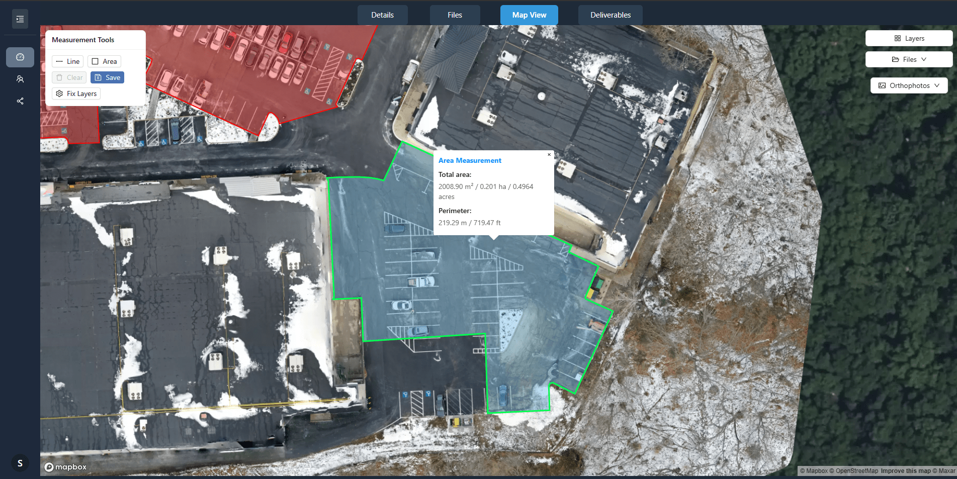
Once the software has computed the relative positions, it refines them into a bundle adjustment. This step simultaneously optimises the camera positions and the 3D coordinates of the matched points. The result is a sparse point cloud that represents the terrain. At this stage, you can also incorporate ground control points (GCPs) - surveyed points on the ground with known coordinates. Adding GCPs dramatically improves the absolute accuracy of the final orthomosaic. If you have no GCPs, the mosaic will still be internally consistent, but its absolute position may be off by meters. For many applications, that is acceptable; for others, such as construction monitoring or property boundary mapping, it is not.
One common mistake is to skip the georeferencing step or to rely too heavily on the drone's GPS. Consumer drone GPS is accurate to a few meters at best. If you need sub-meter accuracy, you must use ground control points or a real-time kinematic (RTK) drone that logs centimetre-level positions. The processing software will show you the estimated error after the bundle adjustment. If the error is large, go back and check for poor matches or missing GCPs.
Step 4: Generate the dense point cloud and digital surface model
After the alignment is stable, the software creates a dense point cloud by matching many more points across the images. This dense cloud is used to build a digital surface model (DSM) - a 2.5D representation of the terrain that includes vegetation, buildings, and other objects. The DSM is essential for the orthorectification step because it tells the software how much each pixel needs to be shifted to correct for terrain relief. Without a DSM, the mosaic would have distortions on slopes and around tall objects. You can inspect the DSM for holes or spikes. Holes occur where no points were matched, often over water, shadowed areas, or very dark surfaces. Spikes are usually caused by moving objects like cars or birds. Many processing tools let you filter the point cloud to remove outliers before generating the DSM.
Step 5: Orthorectify and blend the images
Now the software takes each original photo and projects it onto the DSM, correcting for lens distortion, perspective, and terrain. The result is a set of orthorectified images that all share the same coordinate system. These are then blended (or "stitched") into a single seamless orthomosaic. The blending algorithm decides how to handle the overlap areas: it can average the pixel values, take the sharpest one, or use a more sophisticated method like exposure compensation. You typically have control over the blending mode. For most work, the default setting works well, but if you see seams or colour mismatches, you may need to adjust the exposure compensation or use a different blending method.
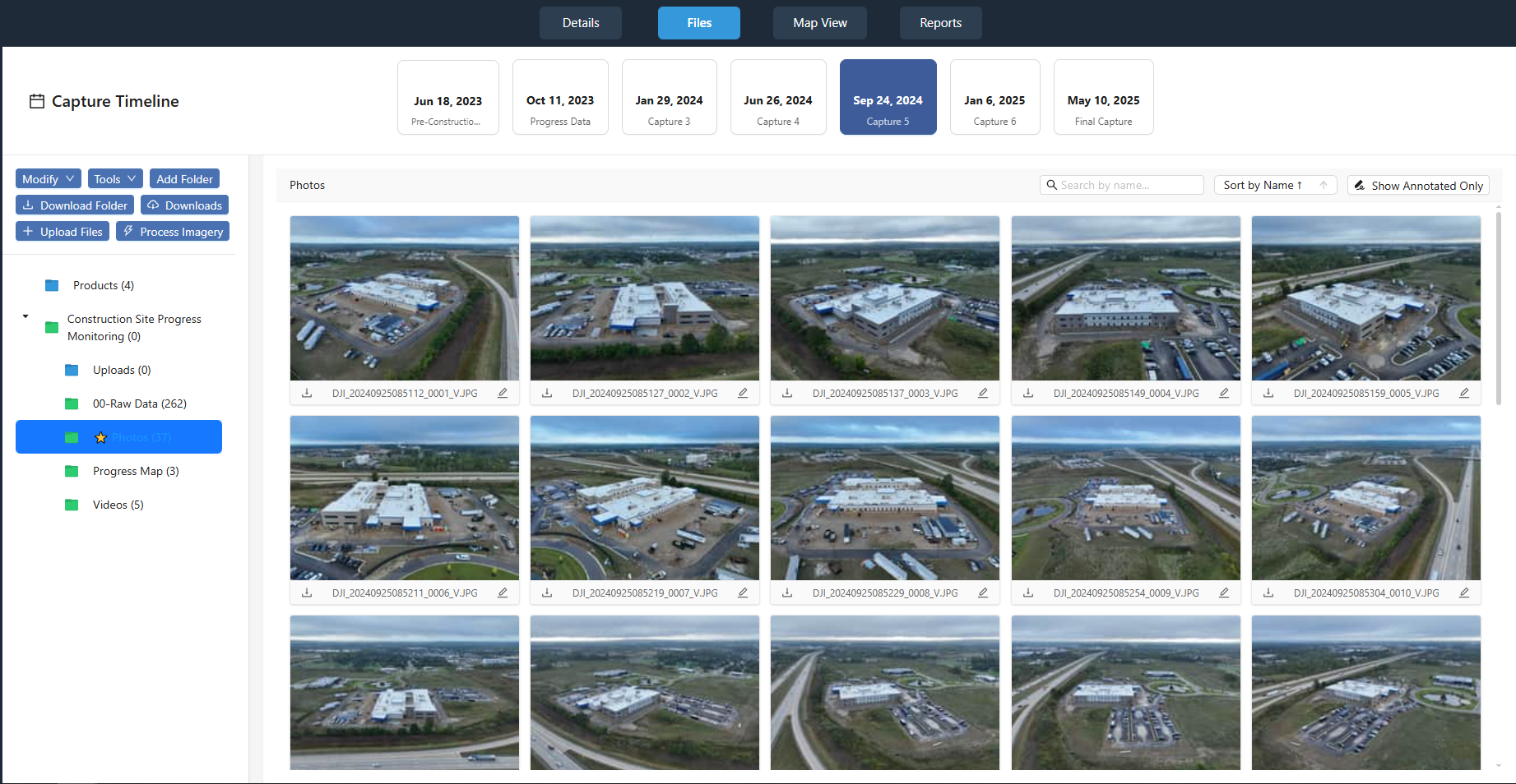
During this step, watch for colour and brightness differences between adjacent images, especially if the light changed during the flight. Many processing tools can perform a global colour balance to even out the image. If the flight was long, the sun may have moved significantly, causing shadows to shift. The software cannot fix that - you would need to fly shorter missions or wait for overcast conditions. Also, check that the coordinate system and projection are set correctly. If you are delivering the orthomosaic to a client who uses a specific local coordinate system, you must set that before the final export.
Step 6: Export and validate the orthomosaic
Export the orthomosaic in a standard format such as GeoTIFF or JPEG 2000 with an embedded world file. Most users need a raster that can be loaded into GIS software or CAD. The export resolution should match your GSD; there is no benefit to exporting at a finer resolution than the source images. After export, validate the result. Load it into a GIS and check a few known points against their expected coordinates. If you used GCPs, the error at those points should be within your tolerance. If you did not, check that the mosaic aligns reasonably with a basemap. Also, inspect the mosaic for artifacts: seams, blurry patches, or missing areas. A small number of defects can often be repaired by re-processing with different settings, but if the flight was poorly planned, you may need to re-fly.
What to watch out for throughout the process
Every step in drone image processing depends on the quality of the input. A flight with insufficient overlap, heavy wind, or poor lighting will produce a mosaic that no software can fully fix. Conversely, a well-planned flight with clean images and good control points can yield an orthomosaic that is accurate to within a few centimetres. The processing software is a tool, not a magic black box: you need to understand what each step does and inspect the intermediate results. If something looks wrong, stop and diagnose before proceeding. There are many resources available, including forums and documentation from the software vendors, and the site nationaldroneservices.net provides a platform for managing and delivering these outputs once they are ready.
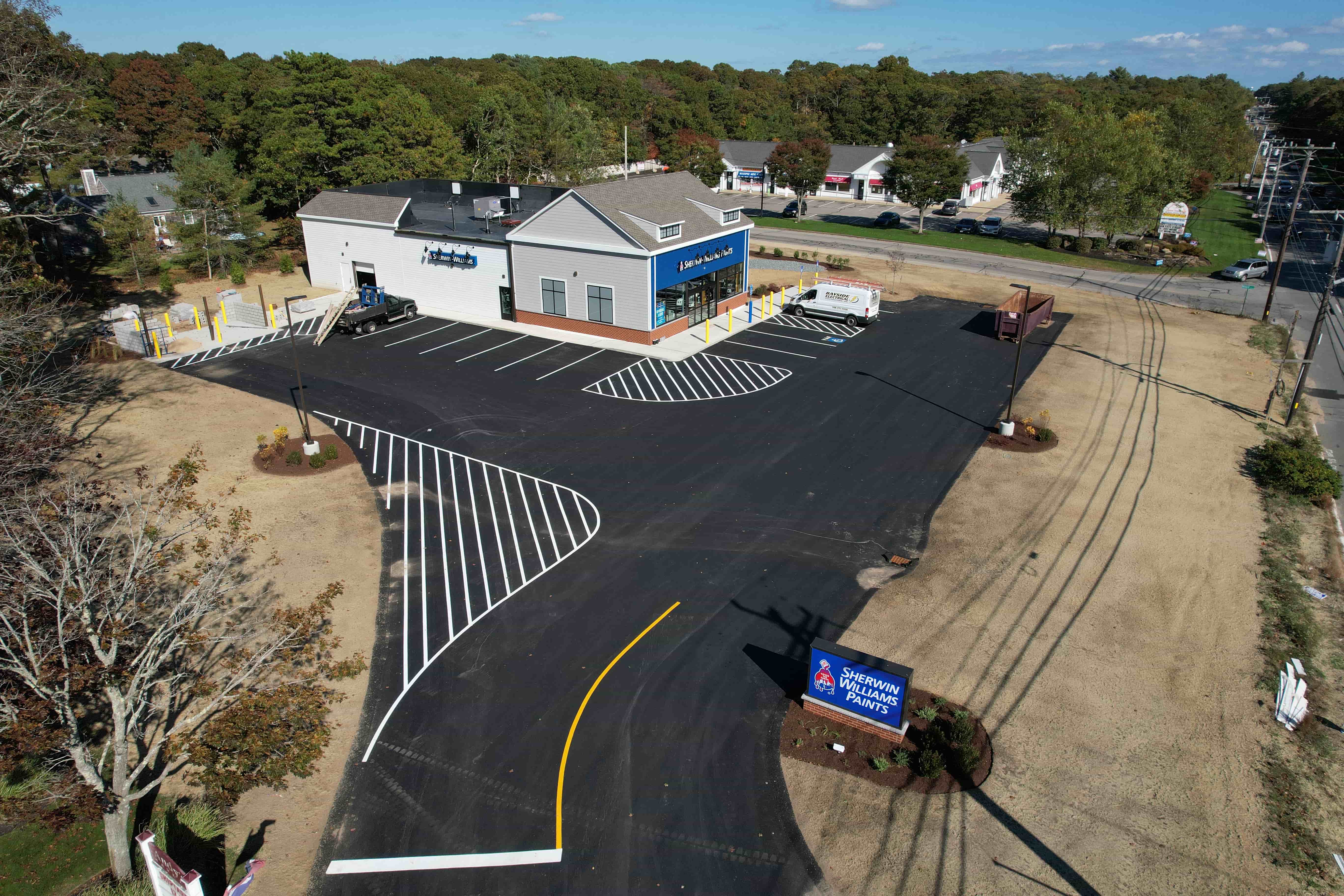
Building an orthomosaic from raw drone photos is a systematic process that combines photography, geometry, and careful quality control. By following these steps and staying alert to the common pitfalls, you can produce a reliable and accurate composite image that serves as a solid base for analysis, mapping, and decision-making. The platform at nationaldroneservices.net can help you organise, view, and share these results with clients through secure portals, making the delivery as smooth as the processing.
Corrections
Spot something wrong? Send it to the desk and it gets fixed in the open.